Board joints
A T-joint and an L-corner that hold sheets of ply or MDF at right angles, with holes for nails, screws and glue. Set your board thickness below and download your own version.
Loading model…
I made these for a toy pony tack locker I’m building out of 5.5 mm ply. Thin ply is too thin to screw into the edge of, so instead of cutting joints, each corner and shelf sits in a printed connector.
There are two shapes. The T-joint holds a board that runs straight through and a second board that butts into its face, like a shelf meeting a side. The L-corner holds two boards meeting at a corner. Every slot is open at its ends, so the boards carry on past the connector. A thin floor underneath joins the walls into one piece, so each connector caps the top or bottom end of a joint.
The holes
- Joint nail holes line up with the end of the butting board. A nail goes through the connector, through one board and into the end of the other, so the boards are fixed to each other rather than just to the connector. The L-corner has them in both outer walls: whichever board you run through to the corner, the nails through that face join the two boards, and the other pair anchors the connector.
- Screw/pin holes fix the connector to each board.
- Glue holes are on the opposite wall, so you can squeeze glue into the slot once the boards are seated.
Panel pins or tacks up to about 1.6 mm thick suit the default 2 mm nail holes. 15–20 mm pins go through the wall and one board, leaving 7–12 mm in the other. The end of 5.5 mm ply leaves only about 2 mm either side of a pin, so drill a 1 mm pilot hole first or it may split.
Getting the fit right
The default slot is 0.1 mm wider than the board, which is a tight push fit on paper. Printed slots usually come out a little narrower than designed, so if the board won’t go in, raise the slot clearance to 0.3–0.4 mm. Measure your board as well: ply is often a little thinner than its label. Before printing a full set, set the grip depth to 12 mm and print one to check the fit.
The printed joints
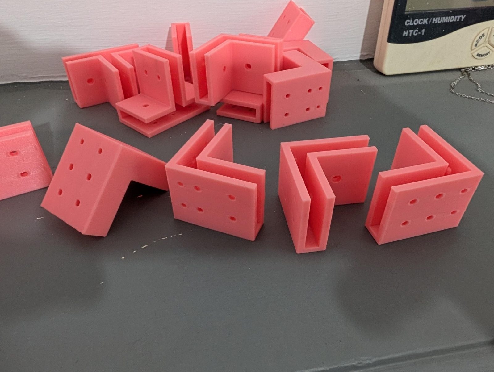
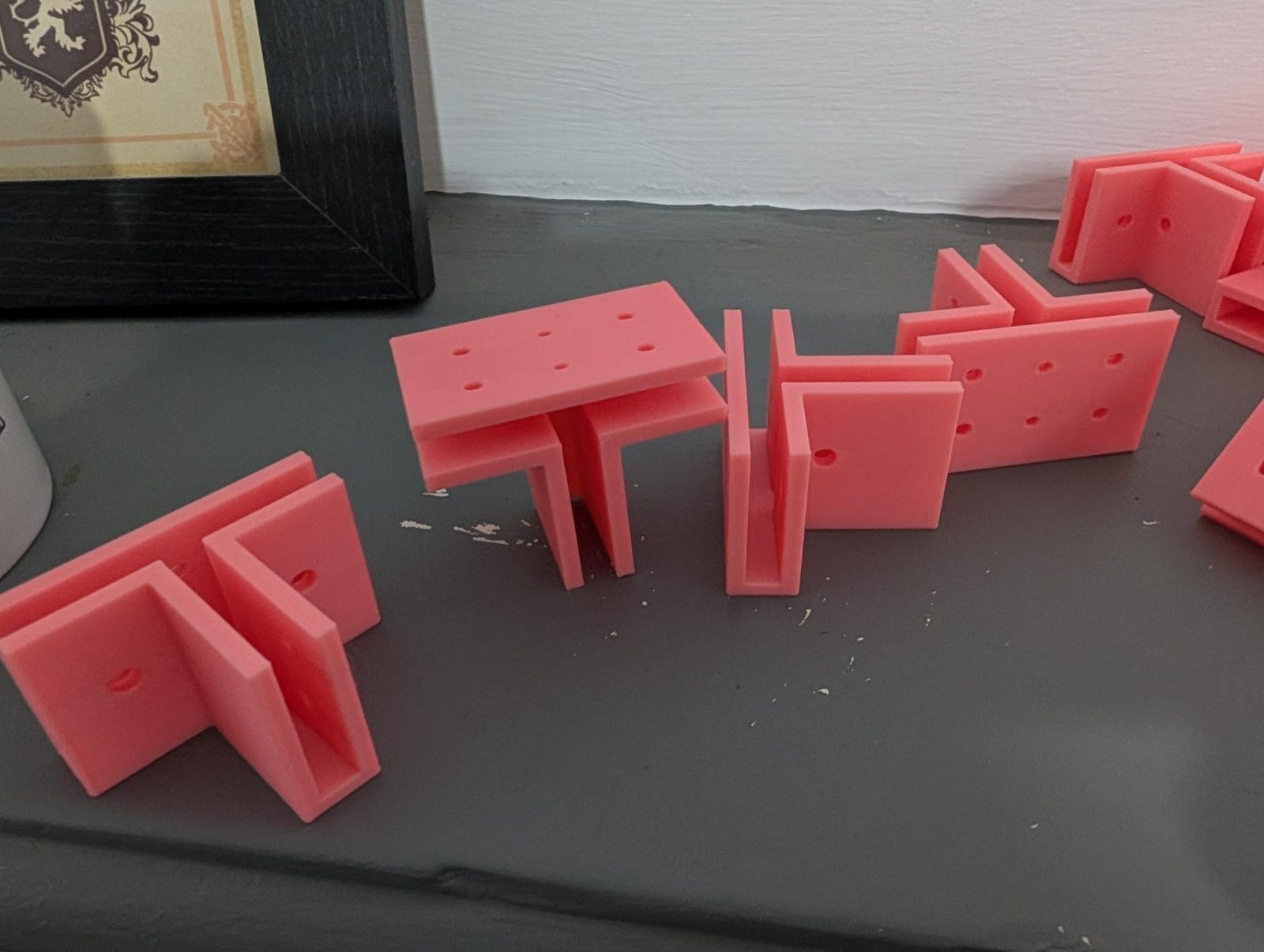
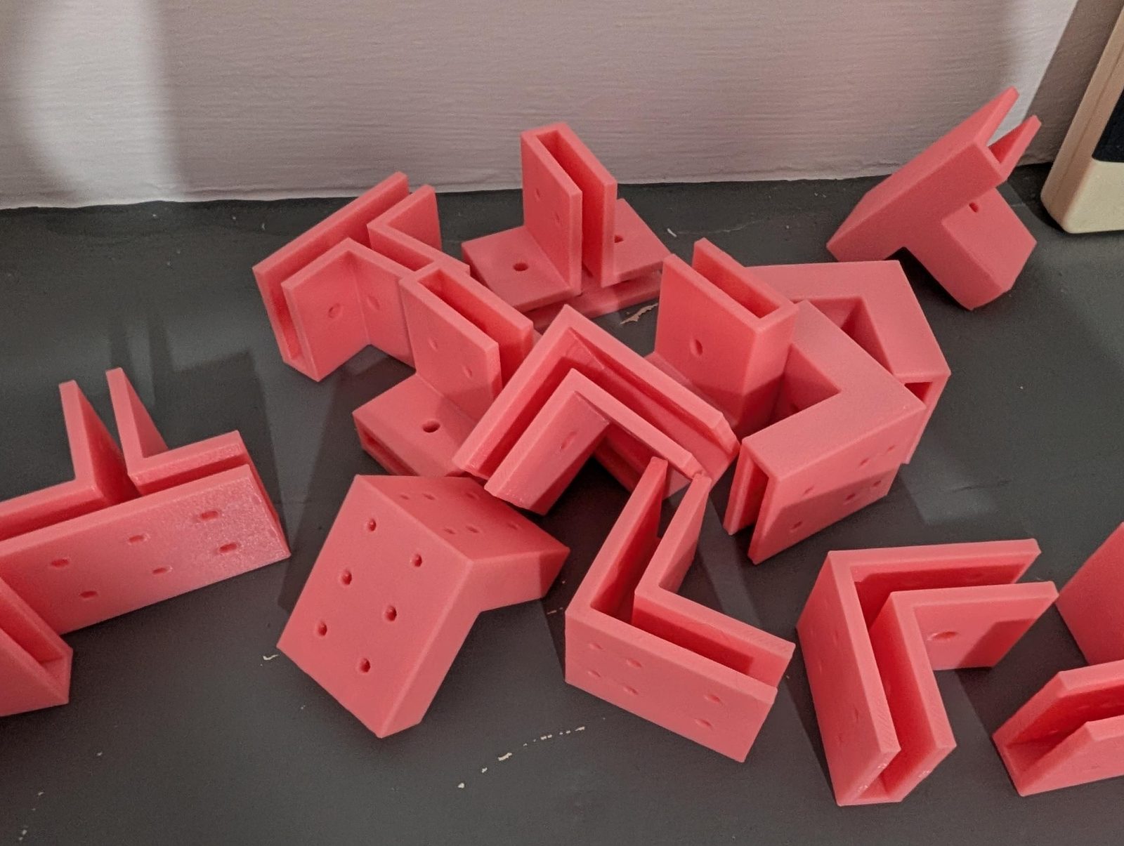
Here’s the first batch.
How it’s made
Like the drill guide, the model is generated in JavaScript with manifold-3d, a geometry library compiled to WebAssembly. The same code made the default file (with node scripts/build-board-joint.mjs) and runs in your browser when you change a value, so the STL you download is made on your own machine. The link from Copy link keeps your settings, so you can share a particular size.